0086-18580036904
0086-23-86194345
0086-18580036904
0086-23-86194345
The working principle of 150 plate and frame pressurized oil purifier pressure sensor is suitable for LY plate and frame oil filter 1800L/H, BASY plate and frame pressurized oil filter 3000L/H, plate and frame oil filter 6000L/H, LY Used for turbine oil purification equipment such as plate and frame oil filter 9000L/H, plate and frame oil filter 12000/H, plate oil filter 18000L/H. The working principle of turbine oil filtration is easy to understand, and the equipment operation is easy to learn.
150 plate and frame type pressurized oil purifier pressure sensor working principle picture:
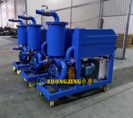
The plate and frame oil filter is specially designed for various power plants, power stations, industrial and mining enterprises, lubricating oil warehouses, tractor stations, petroleum, chemical, metallurgical, defense units, etc., mainly used to filter transformer oil, turbine oil, engine oil, diesel For the moisture and impurities in the oil, stainless steel materials can also be used to filter the vegetable oil.
The filter bed is a continuous operation. Under pressure, the dirty oil is pressed into the filter group that is filtered to the side. It is composed of a set of filter plates and filter frames alternately arranged in sequence, and includes a manual screw pressing device and pressing The composition of the board. There are "ears" on the side of the filter plate and the filter frame to support the pallet of the frame. The filter plate and the filter frame are lined with filter paper or filter cloth as the filter medium. With the pressure of the pressing device, the filter plate and The filter frame is pressed between the fixed thrust plate and the pressing plate of the movable plate, thereby forming a separate filter chamber. The filter paper or filter cloth pressed between the filter plate and the filter frame plays a filtering role. There are two liquid holes at the corresponding positions of the filter plate and the filter frame. When compressed, they form two complete channels. The triangular side of the ears introduces dirty oil. After being filtered by the filter chamber, the other corresponding channels Bring out clean oil.
150 plate and frame type pressurized oil purifier pressure sensor working principle:
1. Install the pressure sensor correctly
The inside of the oil circuit system can be regarded as a sealed communicating container under working condition, obeys Pascal's law, that is, the oil pressure inside the oil circuit system is equal everywhere. In theory, it is possible to install a pressure sensor at any interface in the oil circuit, but in practice this is not the case.
Experiments have shown that the results of installing pressure sensors in different positions are quite different.
In fact, the oil circuit system is not a closed container in an ideal state. There will be leakage in the pipeline, valve body and between the cylinder and the piston, resulting in inconsistent pressure changes at different points.
Secondly, affected by the viscosity of the oil, the transmission of oil pressure has a certain lag. In addition, due to the presence of buffer valves, throttle valves and other components in the oil circuit, the hydraulic oil will fluctuate due to the change in cross-sectional area when the hydraulic oil flows, resulting in different instantaneous oil pressure changes between points.
Again, it is caused by the force of mechanical transmission. When the oil pressure pushes the force measuring piston down, the force generated is counteracted to the piston, causing a large fluctuation in the oil pressure, causing the oil pressure signal detected by the sensor to be unstable.
Therefore, it is necessary to install the pressure sensor in a position that can directly and quickly detect a stable oil pressure signal, accurately reflect the force of the measured object, and have less interference factors.
In addition, try not to take the pressure measuring port from the lower part where contaminants are deposited; it should not be opened in the upper part of the pipeline (valve block) where bubbles are easy to accumulate and the part where the flow rate is fast; the pressure measuring port should be opened on the side of the pipeline as much as possible Use pressure measuring hose to isolate mechanical vibration.
2. Avoid damage to the pressure sensor caused by hydraulic shock
Generally speaking, the peak pressure generated by hydraulic shock can be as high as 3 to 4 times the normal working pressure, and the limit peak value can reach 10 times, which can cause pipeline rupture, hydraulic components and sensors to damage, cause the hydraulic system to heat up, generate vibration, noise, and connections The parts loosen and leak oil, so that the adjustment pressure (set value) of the pressure valve changes.
3. The pressure detection device is used within the range, and the input and output change linearly.
Over-range use will cause plastic deformation of the sensor's strain diaphragm, resulting in a large error in the output value, and the initial residual value is difficult to eliminate. This requires reasonable selection of range in accordance with the accuracy requirements during design. The range should exceed 20% of the maximum pressure (including pressure spikes and pressure fluctuations), and at least 1.2 times the safety valve setting value. For example, a factory has a system pressure of 38 MPa and a sensor with a range of 40 MPa is selected. During commissioning and use, damage to the sensor due to water hammer often occurs. Later, it switched to a 60 MPa range sensor, and there was no fault that damaged the sensor. Usually the selected range is 1.5 to 2 times the actual working pressure. For pressure shock and water hammer occasions, the range can be appropriately expanded without affecting the accuracy and response speed.
4, 150 plate and frame type pressurized oil purifier pressure sensor working principle with appropriate damping
Add damping to the sensor and pressure relay oil ports, which can not only ensure the resolution, but also prevent the sensor strain diaphragm from plastic deformation and failure caused by impact overload. Generally, damping will affect the frequency response of the sensor by about 1 ms to 10 ms. German HYDAC company has special standard 0.3 mm, 0.5 mm, 0.8 mm damping for selection, and also has a standard sensor with 0.5 mm damping. Experiments have proved that 0.5 mm damping has good response performance, can meet most industrial applications, the rise time delay does not exceed 1 ms, and can effectively protect the sensor. For places that require particularly high pressure response, you can install damping during the commissioning stage, and then remove it after the system is operating normally. Note: Damping cannot solve the local high temperature and high pressure impact caused by bubble compression and rupture. Experiments show that if the pressure spike lasts for more than 3 ms, it will cause harm to the sensor diaphragm, and the damping will not play much role.
5, 150 plate and frame pressurized oil purifier pressure sensor working principle to take exhaust measures
When designing, set up reasonable pressure measurement and exhaust joints at the high position of hydraulic cylinders, pipelines, valve blocks, etc., and fully exhaust the system during installation, debugging and maintenance. In the early stage of system debugging, the shock and vibration are relatively large, and the air in the system cannot be fully discharged. The sensitive measuring elements in the system should be temporarily disconnected to confirm sufficient exhaust and the operation is stable before connecting the pressure sensor and pressure relay. Working principle of LY150 plate and frame oil filter pressure sensor
6, 150 plate and frame pressurized oil purifier pressure sensor working principle to formulate debugging and maintenance procedures
Develop debugging and maintenance procedures, fully understand the hazards of hydraulic shock during debugging and use, and proceed according to steps and plans during debugging, which can greatly reduce the damage of hydraulic shock to hydraulic system components, especially pressure detection components. Some on-site commissioning personnel with inexperience have unscientific commissioning schemes. The probability of damage to system components, instruments, pipe joints, etc. during commissioning is obviously high. This requires the full attention of installation units, system plants and users.
Contact: Mr.Zhang
Phone: 0086-18580036904
Tel: web:http://www.zjzklyj.com/
Add: No. 137 Cave Industrial Park, Shapingba District, Chongqing